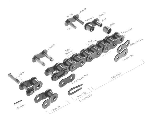
Pitch, Roller Diameter and Inner Width are known as the "Three Basic Dimensions of Roller Chain." When these three dimensions are identical, roller chains and sprockets are dimensionally compatible.
Link Plate
The plate is the component that bears the tension placed on the chain. Usually this is a repeated loading, sometimes accompanied by shock. Therefore, the plate must not only have great static tensile strength, it must also hold up to the dynamic forces of load and shock.
Pin
The pin is subject to shearing and bending forces transmitted by the plate. At the same time, it forms a load-bearing part (together with the bush) when the chain flexes during sprocket engagement. Therefore, the pin needs high tensile and shear strength, resistance to bending, and must also have sufficient endurance against shock and wear.
Bush
The bush is subject to complex forces from all parts, especially from the repetition of shock loads when the chain engages the sprocket. Therefore, the bush needs extremely high shock resistance. In addition, the bush forms a load-bearing part together with the pin and as such requires great wear resistance.
Roller
The roller is subject to impact load as it mates with the sprocket teeth during engagement of the chain with the sprocket. After engagement, the roller changes its point of contact and balance. It is held between the sprocket teeth and bush, and moves on the tooth face while receiving a compression load. Therefore, it must be resistant to wear and still have strength against shock, fatigue and compression. (RS25 and RS35 are bush chains and do not have rollers).
Roller Link
Two bushes are press fit into two roller link plates and rollers are inserted to allow rotation around the outside of the bushes during operation. This is the same for single and for multi strand chains.
Pin Link and Intermediate Plate
The pin link consists of two pins that have been press fit into two pin link plates. In case of multi-strand roller chain up till size 08B, an intermediate plate is added to the pin link. In case of multi-strand roller chain above size 08B, two intermediate plates are added to the pin link. The intermediate plates are slip fit for standard roller chain and press fit for SUPER roller chain.
Roller chains are usually made up of a number of inner and outer links in an endless formation. Although offset links can be used when there is an odd number of links in the roller chain, it is better to use a design that requires an even number of links. If an odd number of links cannot be avoided, it is recommended to use a two-pitch offset link in stead of a one-pitch offset link. As it is riveted into the chain, a two-pitch offset link has a 100% Maximum Allowable Load, where as the one-pitch offset link has a Maximum Allowable Load of 65%.
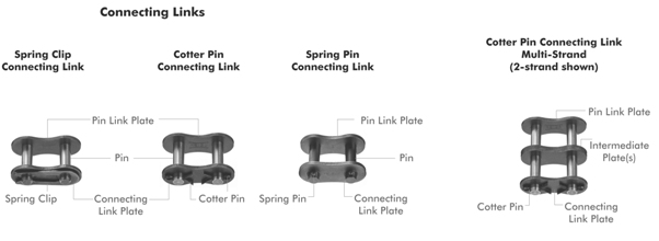
Connecting Links
There are three types of connecting links: spring clip connecting link, cotter pin connecting link and spring pin connecting link.
It's common to use slip fit spring clip connecting links for small size roller chains. Cotter pin and spring pin connecting links are used for large size roller chains and on customer request.
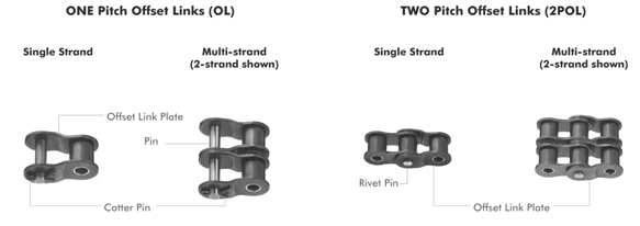
Offset Links
An offset link is used when an odd number of chain links is required. Different types are available:
One pitch offset link (OL).
The pin and two plates are slip fit. The fatigue strength is 35% lower than the chain itself.
Two pitch offset link (2POL).
Two pitch offset links are the combination of a roller link and an offset link connected with a rivet pin. The fatigue strength is the same as the fatigue strength of the base chain. Please refer to the dimension tables for roller chain types and sizes suitable for offset links.